![3_Transparent_Image_footer.png]](https://novineer.com/hs-fs/hubfs/3_Transparent_Image_footer.png?height=32&name=3_Transparent_Image_footer.png)
The color bar and the Value Range (minimum and maximum displacement) are the computed results. The warped mesh is for visualization only: each point is shifted by displacement × Scale.
- Scale = 1.0 → true geometric scale for the solved (linear elastic) displacements
- Scale > 1.0 → exaggerated shape so small motions are easier to see; this is not a new physical solution
You can trust the deformation mode, the location of deformation, and the numeric displacement values. Do not treat a highly scaled warped shape as the part’s real geometry under load.
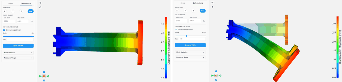
Left: Scale = 1.0 (true geometric scale). Right: Scale = 30.0 (exaggerated so the mode is easier to see).
Left: Scale = 1.0 (true geometric scale). Right: Scale = 30.0 (exaggerated so the mode is easier to see).
Changing Scale does NOT change the simulation. In other words, increasing Scale does not mean a higher applied load, and it does not mean the part has yielded. Yield and failure are judged from failure index and related metrics, not from the warp slider.
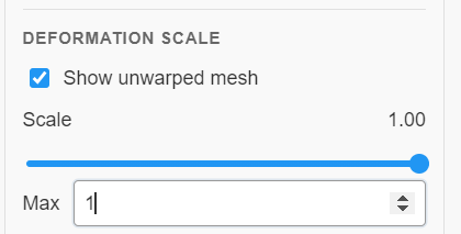
The Deformation Scale controls.
Tip: Keep Max and Scale at 1.0 when you want the outline to match the solved displacement. Raise them only when the motion is too small to see.
Exaggerated warp is also useful to check that the deformation mode looks plausible (for example, bending where you expect it). Near-zero displacement with nonzero loads, or huge unphysical motion, usually means a load or restraint setup problem.
Near-zero displacement with nonzero loads usually means an over-constrained model: see Why are my simulation results all zero (all blue)?.