![3_Transparent_Image_footer.png]](https://novineer.com/hs-fs/hubfs/3_Transparent_Image_footer.png?height=32&name=3_Transparent_Image_footer.png)
The Display toggles show or hide the original model (metallic gray), the finite-element mesh, the toolpaths, the simulation results and the loads and restraints. Face selection only works when the gray geometry is displayed. The Layers panel clips the view at a chosen layer, Render mode shows mesh edges, and the Views menu switches projection and camera orientation.
The Workflow status bar at the top of the plugin window is described in The four-step workflow. This article covers the rest of the viewer.
Display toggles: These buttons show or hide the original geometry, finite-element mesh, toolpaths, simulation results, and loads and restraints. When an item exists and its toggle is highlighted, it is displayed in the 3D viewer.
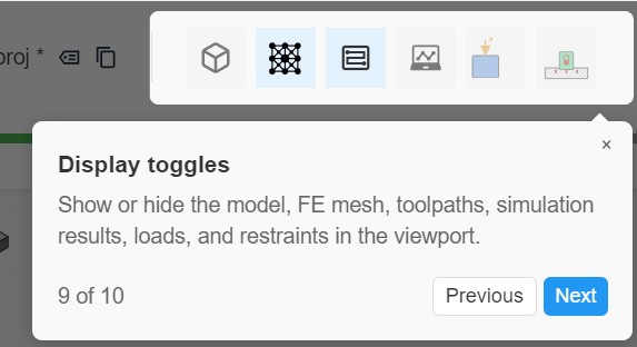
Display toggles
Model geometry: The original CAD or mesh geometry is always shown in metallic gray. The same display is used in Model Setup and in Loads & Restraints. Face boundaries are overlaid on this geometry so you can apply face-selection loads and restraints.
Tip: If you are in Loads & Restraints and do not see this gray geometry, turn off the other Display toggles, then click Model until the gray geometry appears. Face selection will not work without it.

Model display toggle. The metallic gray object is the original CAD or mesh geometry.
Toolpaths: To show or hide toolpaths, or to inspect toolpaths by layer, use the Toolpaths button in the Display toggles panel or the Layers panel on the left side of the 3D view.
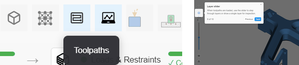
Toolpath and layer display toggles
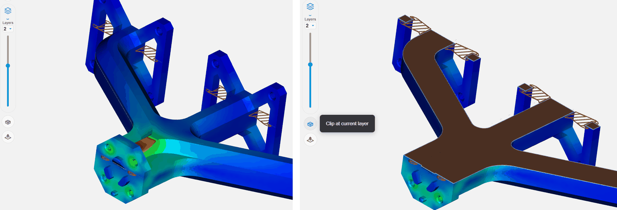
Clip geometry (model, mesh, and simulation results) at the current layer. Simulation results show the outer surface only; clipping does not reveal the interior of the part.
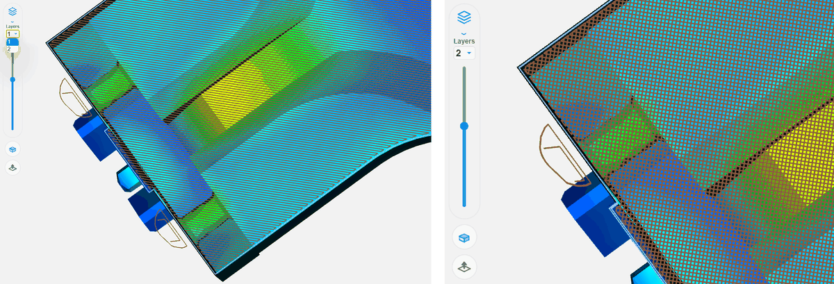
Left: single-layer toolpaths. Right: two-layer toolpaths.
Finite-element mesh: To display mesh edges, open Render mode and click Show edges. When edges are visible, the button tooltip reads Hide edges.
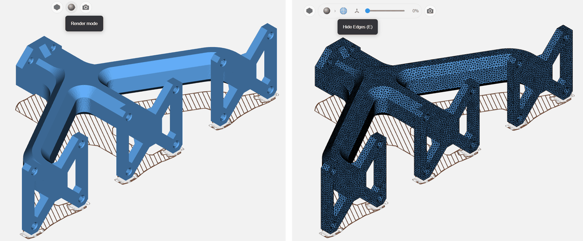
Show and hide finite-element mesh edges
Views menu: Switch between orthographic and perspective projection, and choose camera orientations such as isometric and top.
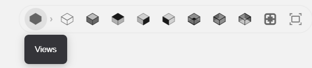
Views menu.
Render mode: Control edge display, transparency, and whether the world origin is shown.
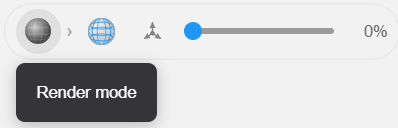
Render mode.