![3_Transparent_Image_footer.png]](https://novineer.com/hs-fs/hubfs/3_Transparent_Image_footer.png?height=32&name=3_Transparent_Image_footer.png)
Load constraints are additional degrees-of-freedom (DOF) constraints applied on the same nodes as the load. They do not replace the force; they limit how those loaded nodes are allowed to move.
Typical uses are test fixtures and grips that hold the loaded end of a part: the fixture prevents some motions of the loaded region while the load acts along the remaining free direction. If the loaded region must be held, add that condition as a load constraint on the load, not as a separate restraint on the same faces, or the result is all zero (Why are my simulation results all zero (all blue)?). The two worked examples below show the difference a load constraint makes.
Worked example 1: the ASTM D7078 shear couponFor example, in a pure ASTM D7078 shear coupon test, the loading fixture resists out-of-plane rotation and bending. The loaded end can translate only along the loading axis. In NoviPath, model that with a Custom load constraint: leave translation free along the load direction and constrain the other DOFs that the fixture prevents.
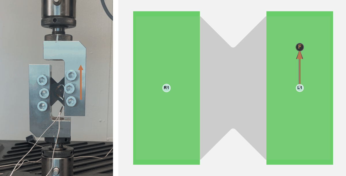
Left: experimental setup. Right: simulation model setup. Properly simulating this ASTM D7078 experiment requires load constraints to prevent out-of-plane bending and torsion.
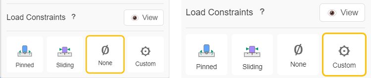
Left: unconstrained loading (incorrect). Right: constrained loading (correct).
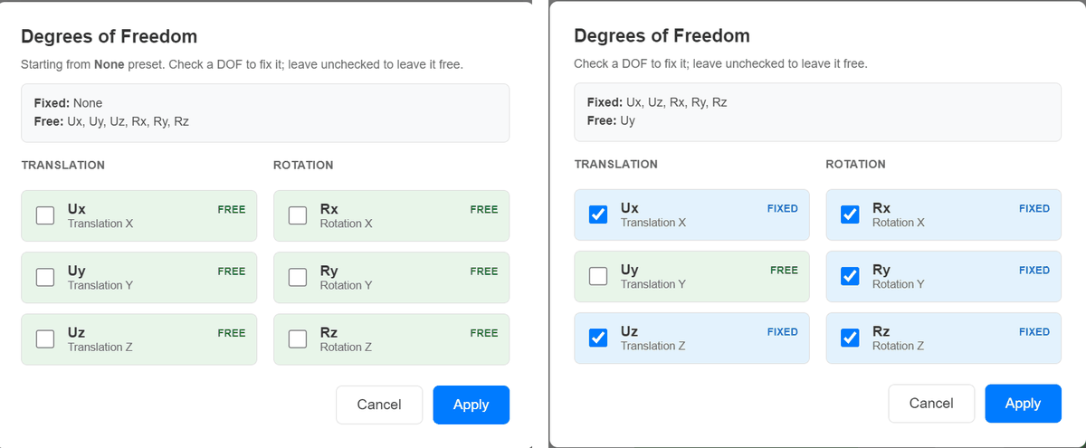
Custom load constraints leave only the vertical translation (Uy) free on the loaded grip.
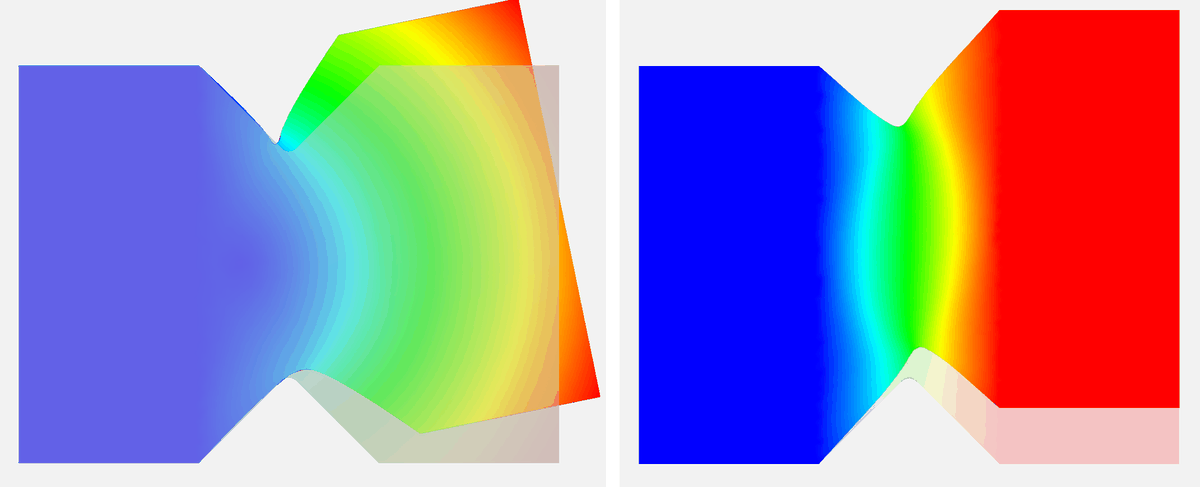
Left: without the constraint the coupon bends and twists out of plane. Right: with the constraint, pure shear in the gauge section.
In this shear coupon model only the Y translation is left free (same as the loading direction). Without that constraint, geometric or mesh asymmetry can produce out-of-plane bending or torsion instead of pure shear in XY.
Worked example 2: Free versus Pinned load constraints under a momentThe example below shows the same idea for a different fixture pattern: a moment applied on a set of nodes that also carry a load constraint. With that constraint set to Free (all translations and rotations free), the loaded end can move and the part behaves like a cantilever under tip moment. With a Pinned load constraint (translations fixed, rotations free), the loaded end stays in place but can rotate — more like a beam with a pinned end under applied moment.
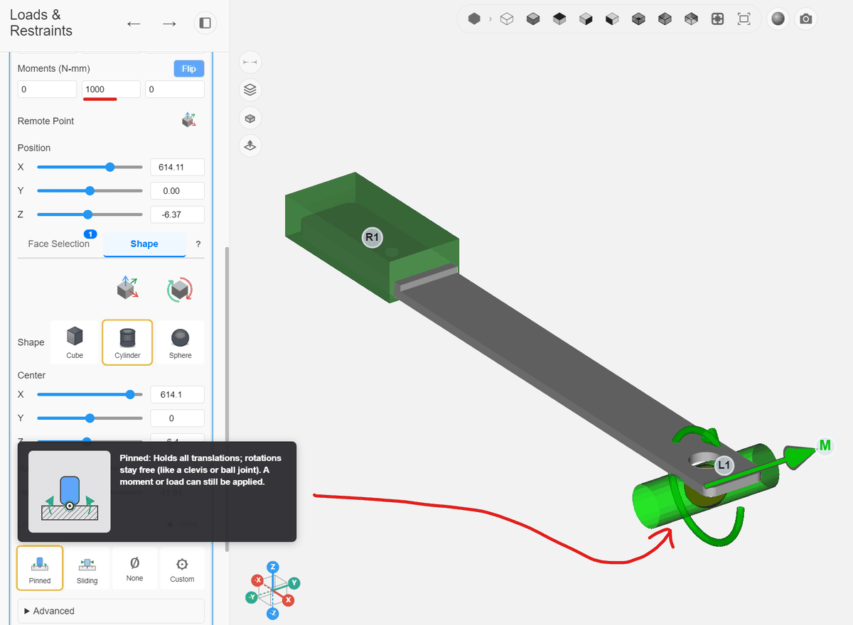
A moment applied on a set of nodes that also carry a load constraint.
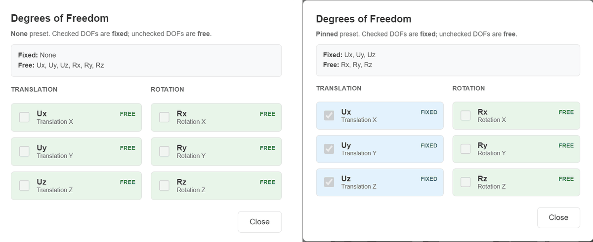
Left: load constraint Free. Right: load constraint Pinned.
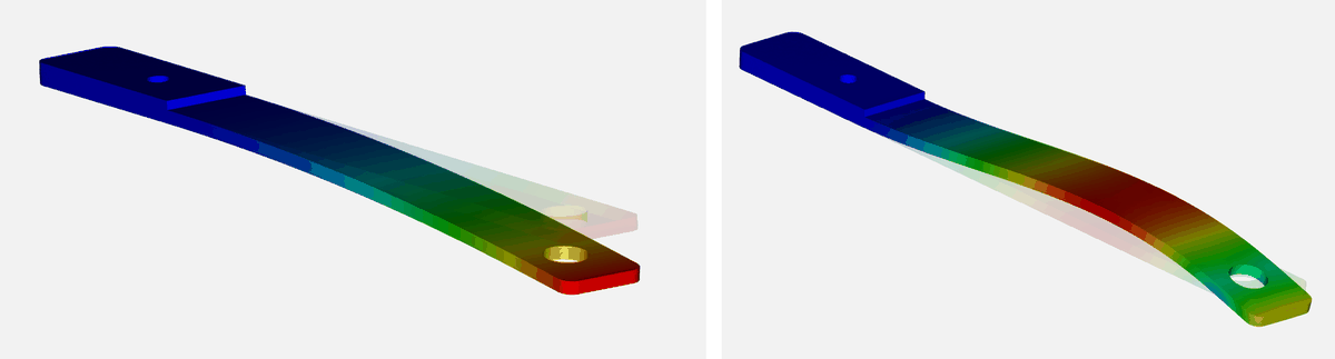
Left: load constraint Free, the part behaves like a cantilever under tip moment. Right: load constraint Pinned, the loaded end stays in place but rotates.