NoviVision helps you turn a set of guided part photos into 3D models by walking you through two connected stages:
-
Use mobile app to create a project and capture the required reference photos (and optional extras) in the mobile app
- Use NoviVision Hub to generate a model, scale it, repair it, and download/export results
Stage 1: Mobile App Setup and Image Capture
1. Initial Setup and Syncing
 Connectivity: After logging in, ensure you have an active internet connection. To work offline, you must create a project at least once and visit both the metadata and photo pages while still online. After that, you can be offline.
Resuming Work: If you want to pull down existing projects (instead of starting from scratch):
- Open the menu in the mobile app and select Sync.
- In the Data Sync screen, use filters like:
-
- Part Number
- Tags
- Date Range
- If no filter is selected, then all the data available in the NoviVision hub is synced.
- Tap Search, select the results you want
- Tap Sync to bring those projects into your device list.

 Downloading Photos: For synced projects, enter the project and tap Download to view previously stored cloud photos locally.
2. Creating a New Project
Project Initiation: Tap the floating (+) button to start a fresh project
Metadata Entry: Fill out the metadata form; note that specific fields vary by industry type. Tap Save & Continue to proceed to the camera interface.

3. Capturing the Photo Set
To generate a model, you must provide one of two required sets:
- Single Image: One isometric view of the part.
- Multiple Images: Four high-quality images consisting of Front, Back, Left, and Right views.
Providing both sets allows you to generate two separate models.
For each slot, tap it (e.g., Front). You can either use the app capture, or use phone camera that has higher resolution, or choose from the phone photo library, or from a file.

Choose a front and then rotate the part 90° clockwise (or the camera 90° counterclockwise) between each of the four required shots
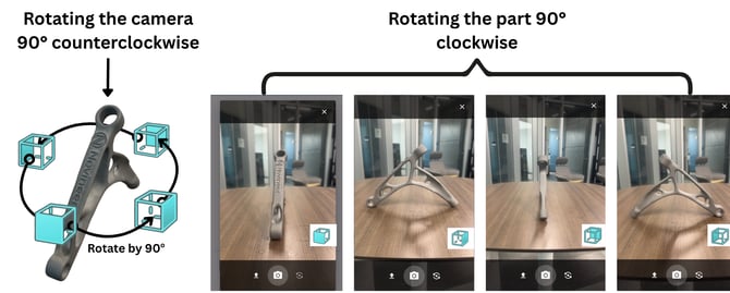
Any frame can be selected as the front view. The important thing is to pick a “Front” view that you can keep consistent across the remaining views.

For thin parts, capture the front and back from a tilted view for better definition

If you must hold the part, use the smallest touch possible with your finger so it can be easily cropped out later

 Optional Scaling Photo: Capture one photo of the part placed on or beside an A4 sheet of paper. Ensure the part is on a flat surface and that all four corners of the paper are visible.
After capturing images, NoviVision provides an Image List view where you can open an image and Crop it to better frame the part


Use the EXTRA PHOTO button if you need supplemental views for model generation or to Request a Parametric CAD

After you are done with all the photos, tap Save
4. Local vs Cloud projects
 Your project list shows a status label (e.g., Local vs Cloud) and the number of photos attached. For the photos stored locally, you can tap UPLOAD to sync with the cloud.

You can upload multiple projects simultaneously. In the search view, filter for Local projects, then use Upload All to push them to the cloud so they’re available in NoviVision Hub.
Stage 2: Processing in NoviVision Hub
Dashboard
Open NoviVision Hub. In the Dashboard, use Sync to pull the latest projects/images uploaded from mobile. Enter the project

You can use the Export button in Dashboard to export the metadata and a link to download all the models related to the selected project.

Generator Input
 In the Metadata page, review the data. If you update the data, sync it to the phone later to keep the data consistent. Then tap next.
In the Hub’s Generator Input screen:
- Review the uploaded image set
- Confirm each image is correctly assigned to its view label (Front/Back/Left/Right, etc.)
- Choose Generator Mode (shown as options like Single or Multiple)
- Click Save & Continue

In the Model Generator tab, click Generate Model. Once generated, the model appears in the 3D viewer.


After the model is generated, you can scale the model. Open Measured Size tree
- Click Show OBB to visualize the bounding box
- Apply VL/VW/VH
- Enter your real-world measured value for at least one dimension in the panel.
- Click Apply Scale to apply the corrected scale to the model.

Model Repair
Repairing Edges: If the generated STL has non-manifold edges, select the model (Scaled or Unscaled) and click Repair Model.

B-Rep Conversion: To create a CAD-ready model, select a file (Unscaled, Scaled, or Repaired) and click the Convert Stl to Brep button.


You can view (eye icon) and download each of the models
If you want to supplement generated geometry with an externally prepared STL/STP, so you have all the models in one place, you can use Upload STL/STP
Parametric Requests: If you need a more editable output, click Request Parametric CAD and provide a short note describing the dimensions or details needed. You can track the status of this request in the Dashboard.

Feedback: The Model Repair page includes a simple feedback control to share your experience with the generated models. Select Satisfied or Unsatisfied, then click Send
