![3_Transparent_Image_footer.png]](https://novineer.com/hs-fs/hubfs/3_Transparent_Image_footer.png?height=32&name=3_Transparent_Image_footer.png)
NoviPath provides Fixed, Pinned, Roller, Slide and Custom restraints. Slide resolves to Guided on a planar face, Cylindrical on a hole or cylinder, and Slide on a shape or mixed selection. Click View on a restraint to see which DOFs are fixed and free, and use the Render mode toggles to show them in the viewer.
NoviPath supports five restraint types: Fixed, Pinned, Roller, Slide and Custom. Click View on a restraint to see the fixed versus free DOFs for the current type.
The Slide type resolves to Guided, Cylindrical, or Slide depending on the kind of face or shape you selected (planar face, cylindrical face, or a shape).
The restraint type selector: Fixed, Pinned, Roller, Slide, Custom.
Roller
When: Face mode with a planar face. Frictionless support on that surface.
| Free | Fixed |
|---|---|
| Both in-plane tangents; rotations free | Motion through the surface (face normal) |
Example: a part resting on a flat table or plate. It can slide sideways on the face but cannot push through the support.
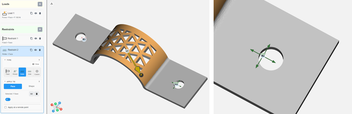
Left: a Roller restraint on the planar face at the right end of the clamp. Right: close-up of the free in-plane directions.
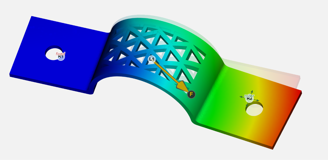
The resulting deformation with the Roller support.
Guided (Slide on a planar face)
When: Face + planar face, then Slide. UI label: Guided.
| Free | Fixed |
|---|---|
| One in-plane direction (Us), projected onto the face; rotations free | Face normal and the other in-plane tangent |
Set the free direction with the tray snaps or Aim (the result is projected onto the face). The direction follows the part on reorient or import.
Example: a slot or rail on a flat pad. The part can move only along the slot in the face plane, like a guided frictionless support.
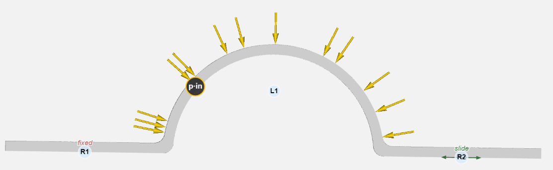
Pressure on the top surface of the clamp; R1 on the left is Fixed and R2 on the right is a Guided slide on the bottom planar surface, free only along the slide arrow.
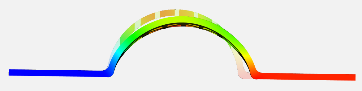
The part before (gray) and after deformation.
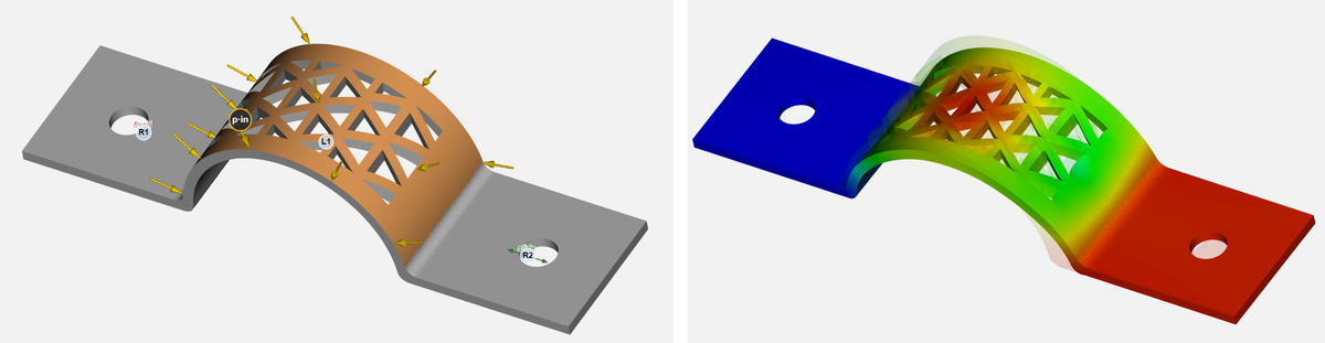
Left: the Guided restraint setup in the 3D view. Right: the deformed shape.
Cylindrical (Slide on a cylinder or hole)
When: Face + cylindrical face(s) with a shared axis, then Slide. UI label: Cylindrical.
| Free | Fixed |
|---|---|
| Slide and spin about the free direction (Ua, usually the hole axis) | Radial and perpendicular motion, and tilt |
Aim or edit the free-direction vector (typically the hole axis). Works for holes and outer cylindrical faces. The direction follows the part on reorient or import.
Example: a pin or shaft in a bore, free to slide along and rotate about the hole axis, but unable to tilt or move sideways. In the example below, the second restraint R2 is applied to the bolt hole on the right and the sliding direction is set along the axis of the cylindrical hole. This is equivalent to the second hole being held by a smooth frictionless pin that is held vertically.
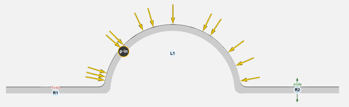
R2 is a Cylindrical slide on the right-hand bolt hole; the free direction is the hole axis.
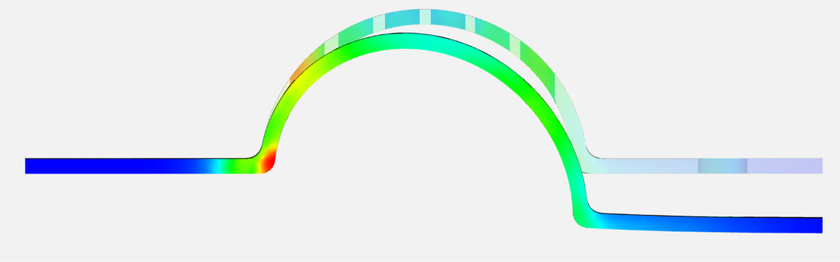
The part before (gray) and after deformation.
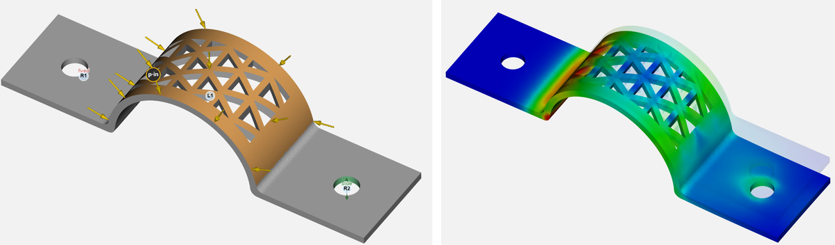
Left: the Cylindrical restraint setup in the 3D view. Right: the deformed shape.
Note: If multiple faces are selected and they have different hole axes, the UI falls back to tray Slide. In that case, split the restraints into one restraint per shared axis for true hole-axis sliding.
Slide (tray, shape or mixed)
When: Shape selection is on, or Face selection is on but is not a single planar or cylindrical set. UI label: Slide.
| Free | Fixed |
|---|---|
| One direction (tray X/Y/Z, shape axis snaps, or Aim vector) | Other translations and all rotations |
Example: a prismatic rail along tray X on a shape region, or a mixed-face patch that should only move along one global or Aim direction.
Custom
When: either Shape or Face selection is on. Custom allows the highest level of control over all six degrees of freedom.
Depending on the selected item, an additional Local button appears in the dialog. For a planar face, the Local option presents translations along the in-plane tangents (Ut1, Ut2) and the surface normal (Un). For a cylindrical face, these options are aligned with the radial directions (Ur1, Ur2) and the axial direction (Ua). Rotations are correspondingly applied about those axes. For all other face types, only the Global option is available.
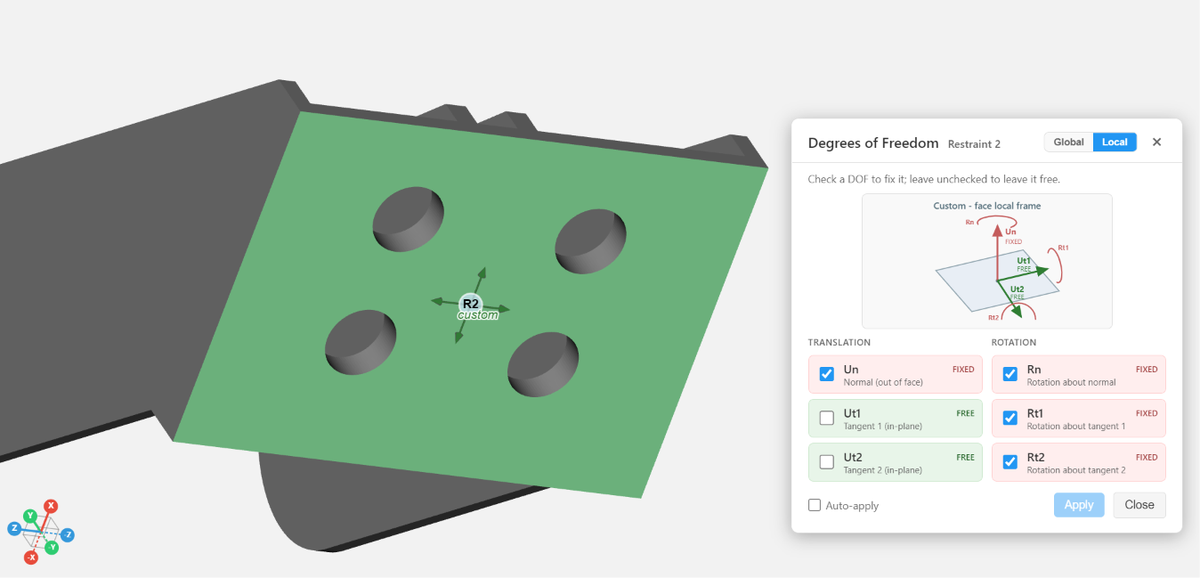
A roller-like constraint specified with Custom by freeing Ut1 and Ut2 on a planar face that is oblique with respect to the global coordinates.
Quick comparison
| Type | Selection | Free motion | Typical physical analog |
|---|---|---|---|
| Roller | Planar face | Both tangents; normal fixed; rotations free | Flat pad or table |
| Guided | Planar face + Slide | One in-plane direction; rotations free | Slot or guided rail on a face |
| Cylindrical | Cylinder or hole + Slide | Slide + spin about the axis; tilt fixed | Pin in a bore |
| Slide | Shape or other faces | One tray or Aim direction; rotations fixed | Prismatic joint or linear rail |
| Pinned | Any | Rotations free; translations fixed | Clevis or ball joint (no translation) |
| Fixed | Any | Nothing free | Welded or fully clamped |
Visualizing restraints
Expand the Render mode panel to see toggles that turn the Fixed and Free translations and rotations on and off.

The Render mode toolbar.
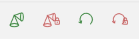
The restraint toggles, in this order: Free translations (green cones) | Fixed translations (red cones with lock) | Free rotations | Fixed rotations.
Never place a restraint on faces that already carry a load in the load direction: the result is all zero. See Why are my simulation results all zero (all blue)? and, when a fixture must hold the loaded region, the load constraints in Applying Force, Moment, or Pressure.