Lbracket Optimization
Geometric and Toolpath Design and 3D Printing of Strength-Optimized Parts Using Continuous Fiber Reinforced Composites
Industry
Aerospace
Novineer Capabilities
Strength Optimization
Toolpath generation
Anisotropic Properties

Fiber paths automatically designed
significantly reducing engineering time

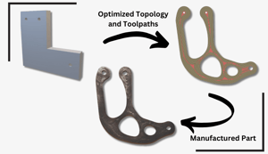
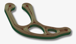
LBracket topology and toolpaths were optimized to reduce its weight while simultaneously maximizing its strength effectively. Optimized fiber paths were automatically generated by considering the material properties and manufacturing constraints, such as layer height, minimum filament turn radius, and fiber spacing. As a result, fewer iterations were needed to produce an optimized part from concept to print, thereby reducing engineering design time.
Stronger components produced
while saving weight
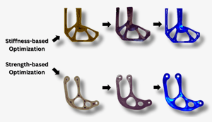
The original L bracket was optimized for maximum strength given a downward loadof 2500N. The Tsai-Wu yield criterion and the anisotropic properties of continuous fiber composites were implemented in the optimization process. The bracket produced was able to withstand twice as much load per volume compared to that produced by typical stiffness optimization. The stiffness-based optimization method resulted in a design with a sharp corner that led to premature failure. In contrast, the strength-based optimization led to rounded corners and lower stress concentrations.

Guaranteed part performance
validated against industry leading FEA software

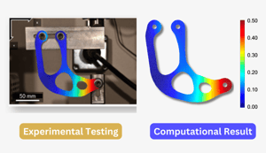
The optimized strength-optimized bracket was experimentally tested and compared to experimental evaluation. Composite parts were manufactured by using continuous carbon fiber reinforced (CCF) filaments. Each CCF filament is 1mm wide and contains continuous AS4 carbon fibers in a polyetherketoneketone (PEKK) matrix, with a fiber content of 60 ± 2 vol.%. The measured stiffness and strength are reported below.
| Property | Experimental | Computational | Error |
| Stiffness (N/mm) | 4970 | 4770 | 4% |
| Strength (N) | 4910 | 4680 | 5% |

