
Entering design input, designing the part, and generating toolpaths for 3D printing
Design Input
The first step in the design module is entering the design inputs including
Print Specifications (This option is only applicable for the 'Geometry and Toolpaths' Design Type)
Suppose 'Geometry and Toolpaths' Design Type was selected when a project was created. Then, the print specifications, such as layer thickness (height), filament width, minimum length of filament, and minimum radius of filament, need to be entered. These parameters are based on your Fused deposition modeling (FDM) 3D printer and material specifications.
Print Orientation
This applies to both 'Geometry and Toolpaths' and 'Geometry' Design Type. The direction the part is being printed. If the direction changes during the printing process, then choose the dominant direction here.
Design Methodology
Optimize Performance + Editability(stp): In the methodology, the performance is optimized using discrete geometric elements to ensure the optimized model is Editable. If this option is selected, then the number of pieces that will be considered in the design process should provided. 16 pieces will result in a lower resolution but more manageable, 32 pieces will result in a a higher resolution but less manageable,
Maximize Performance(stl): The performance is maximized subjected to volume fraction constraint. Since editability is not considered in the design process, the design results in many surfaces that are difficult and sometimes impractical to convert to stp format. You can see two examples below.
💡 You can choose both 'Maximize Performance' and 'Optimize Performance + Editability' options. If you choose both, you will have both STL for maximized performance and STP for Optimize Performance + Editability.
Let’s Save and continue to Start Design.
Start Design
Your selected option(s) for the design methodology are shown. The estimated core hours and estimated time for the design task are shown. Please keep in mind that these are estimations; the actual time varies based on the complexity of the model and the network speed. Of course, the actual number of core hours after the design is done will be reduced from your available core hours. If you'd like to learn more about the core hours for various cases, please take a look at this article.
After the design task is done, let’s Save and continue to Optimized Design.
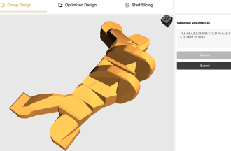
Group Design
If the "Optimize Performance + Editability (STP)" design method is selected, the optimized shapes and their locations are displayed within this tab. To view them, click the "Preview and Edit Discrete Geometries" button. The Novineer algorithm automatically groups different pieces. You can modify these groups to generate a design with smoother transitions and fewer volumes.
💡 Non-design volumes are not displayed in this view but will be reintroduced when the grouping is complete and the STP file is generated.
After selecting your desired groupings, click "Generate STP" to create the STP model based on these selections.
Below are two different grouping examples for the GE case study:
1. First Grouping: As shown in the figure on the left, five groups are created. This results in the STP model shown on the right, where part of the geometry is highlighted.
 .
. 
2. Single Group: All discrete geometries are combined into one group, as depicted in the left animation. This generates the STP model on the right, featuring a smoother transition between the different pieces.
Once the STP model is generated, click "Save and Continue" to proceed to viewing and downloading the Optimized Design.
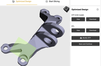
Optimized Design
The items in this section depend on the selected option in the selected option for Design Methodology.
If 'Optimize Performance + Editability (stp)' was selected
STP is available to be downloaded.
If 'Maximize Performance(stl)' was selected
Only STL is available to be downloaded.
If both options are selected
STP for design provided by 'Optimize Performance + Editability (stp)' Design Methodology and
STL for design provided by 'Maximize Performance(stl)' Design Methodology are available to be downloaded
💡 The next step (slicing) is only available if 'Geometry and Toolpaths' Design Type was selected when a project was created. If this option is selected, you have the option to modify the STL or STP in your CAD software and upload the Modified STP for the slicing. For the torque link test case, we presented the modifications in our case study.
%20(1).png?width=688&height=378&name=Quickstart(Tutorial)%20(1).png)
Start Slicing
The items in this section depend on the selected option for Design Methodology and Optimized Design.
If Modified STP is uploaded, regardless of selected Design Methodology option
Slicing will occur based on modified STP
Otherwise,
If one of 'Optimize Performance + Editability (stp)' or 'Maximize Performance(stl)' options is selected
The slicing will be performed based on stp or stl respectively
If both options are sleeted
Here you have the option to select whether you want the slicing to be performed with respect to Maximize Performance(stl) or Optimize Performance + Editability (stp)
By pressing Start Slicing, the toolpaths are generated. After toolpaths are generated, You can see the toolpaths for all the layers. You can download them, or alternatively, you can see toolpaths for individual layer.
.gif?width=688&height=378&name=Quickstart(Tutorial).gif)