![3_Transparent_Image_footer.png]](https://novineer.com/hs-fs/hubfs/3_Transparent_Image_footer.png?height=32&name=3_Transparent_Image_footer.png)
You have two ways to choose where loads and restraints are applied — that is, which nodes of the finite-element mesh receive them.
Key terms: Finite-element analysis (FEA) represents the part as a mesh of nodes. A degree of freedom (DOF) is one allowed motion at a node — typically three translations (UX, UY, UZ) and three rotations (RX, RY, RZ). Loads apply forces or moments to selected nodes; restraints constrain selected DOFs (fixed or free).

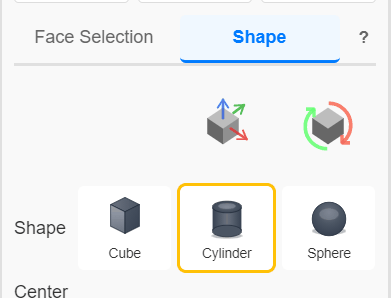
The Face Selection and Shape tabs of a load or restraint.
All components are entered in the tray (global) X, Y, Z system, not along a face normal: see Loads are defined in tray XYZ, not surface normal.
Face Selection
- NoviPath identifies analytical surfaces (for example planar, cylindrical, and toroidal faces) on the original model. You can apply loads and restraints to all surface nodes that belong to those faces.
- Whether you imported a native CAD part (such as a SolidWorks *.sldprt file), a STEP file, or an STL, the plugin receives a 3MF mesh from the GrabCAD API and then identifies analytical surfaces and edges on that mesh. Face selection is therefore available regardless of the original geometry format.
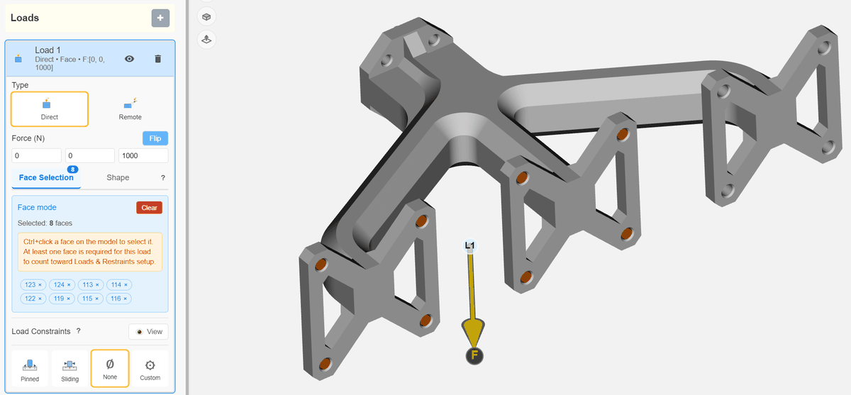
Applying loads and restraints using Face selection. Ctrl + click on a face to select.
Shape
- This option lets you place a cube, sphere, or cylinder and apply the boundary condition to every surface node that falls inside that shape.
- To apply the same load on the eight bolt holes shown above with Shape mode, you would create eight separate shape loads.
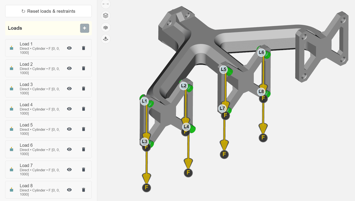
Applying loads and restraints by selecting a Shape. All the surface nodes that fall within the selected shape will receive the loads/restraints. Loads are distributed uniformly across all those nodes.
When to Use Face Selection versus Shape- As evidenced by the previous end-of-arm-tool example, Face selection is the fastest and easier approach for many geometries where you want to apply a distributed load or common restraint to multiple disjoint faces. However, there are other situations where Shape type loads/restraints would be needed –
- If the faces NoviPath has recognized and identified do not match the region where the load or restraint actually acts, use Shape instead. For example, when you want to apply loads on a portion of a flat face rather than the entire face. Or load a small portion of a cylindrical surface.
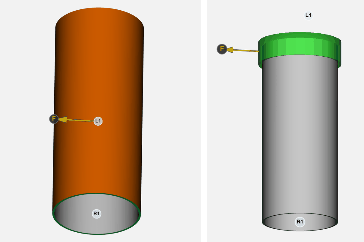
Left: Face selection for the load, the entire cylindrical surface is selected and all the nodes on that surface receive the distributed load. Right: Shape type for the load, all the surface nodes of the gray part that fall within the green cylinder receive the distributed load. Use a Shape when the actual load is applied only to a portion of a face.
Which Definition Is Used if Face Selection and Shape Both Have Values?- The simulation uses Face selection whenever that list is not empty. Shape is used only when Face Selection is empty. Switching to the Shape tab does not clear the face list.
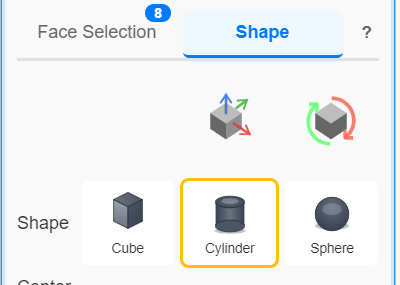
Face selection contains 8 items, so those faces are used even though the Shape tab is active.
In the above image, Face selection contains 8 items, so those faces are used even though the Shape tab is active. Clear the Face Selection list if you want the Shape definition to be used instead.
Face selection has 0 items, so the Shape values are used.
In the above image, Face selection has 0 items, so the Shape values are used.