![3_Transparent_Image_footer.png]](https://novineer.com/hs-fs/hubfs/3_Transparent_Image_footer.png?height=32&name=3_Transparent_Image_footer.png)
A tight range between the Min and Max Edge Factors produces a larger mesh and longer meshing and solve times; small changes can change the element count dramatically, especially on curved geometry. With the minimum edge length held constant, increasing the maximum reduces the tetrahedral count. Keep Min Edge Factor near 2 when through-thickness toolpath effects matter.
This section discusses a mesh sensitivity study to illustrate the effect of edge factors on the mesh size and simulation results. Edge-factor definitions and recommended defaults are in Meshing; here we show how changing Min Edge Factor and Max Edge Factor affects element count, runtime, memory, and predicted Max FI / displacement.
Two variations on the same geometry illustrate the effect:
- Keep the Min Edge Factor constant while increasing the Max Edge Factor (which also increases the Average Edge Factor). See the first chart below for the effect on mesh size (vertical axis).
- Keep the Average Edge Factor constant while increasing the Min / Max range. See the second chart below for the effect on mesh size.
A tight (small) range between the Min and Max Edge Factors typically produces a larger mesh and longer meshing and solve times. Small changes can increase element count dramatically, especially on highly curved geometry and at the low end of the range. For instance, in the first chart, reducing Max Edge Factor from 3 to 2.5 while holding Min Edge Factor at 1.5 approximately doubles the mesh from 2 million to 4 million tetrahedra.
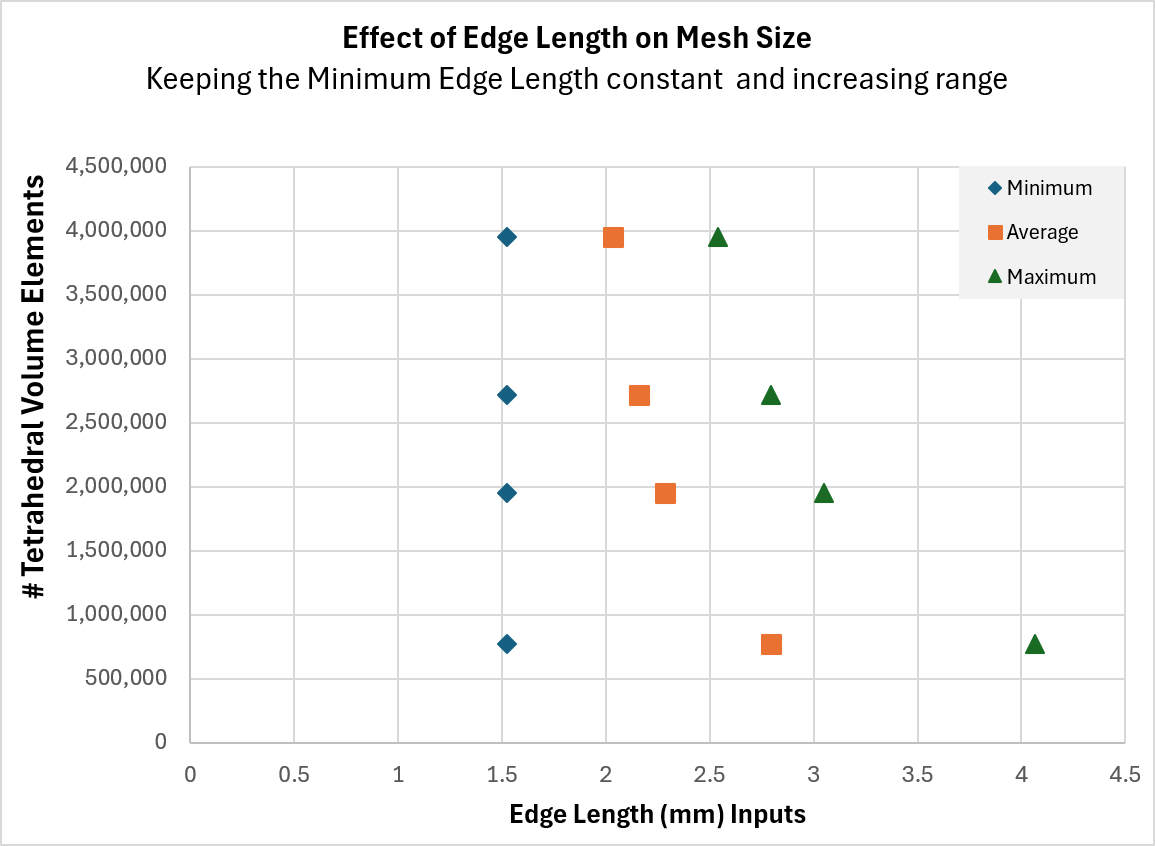
Effect of edge-length range on mesh size. Only Max Edge Factor is changed; Min Edge Factor is held constant.
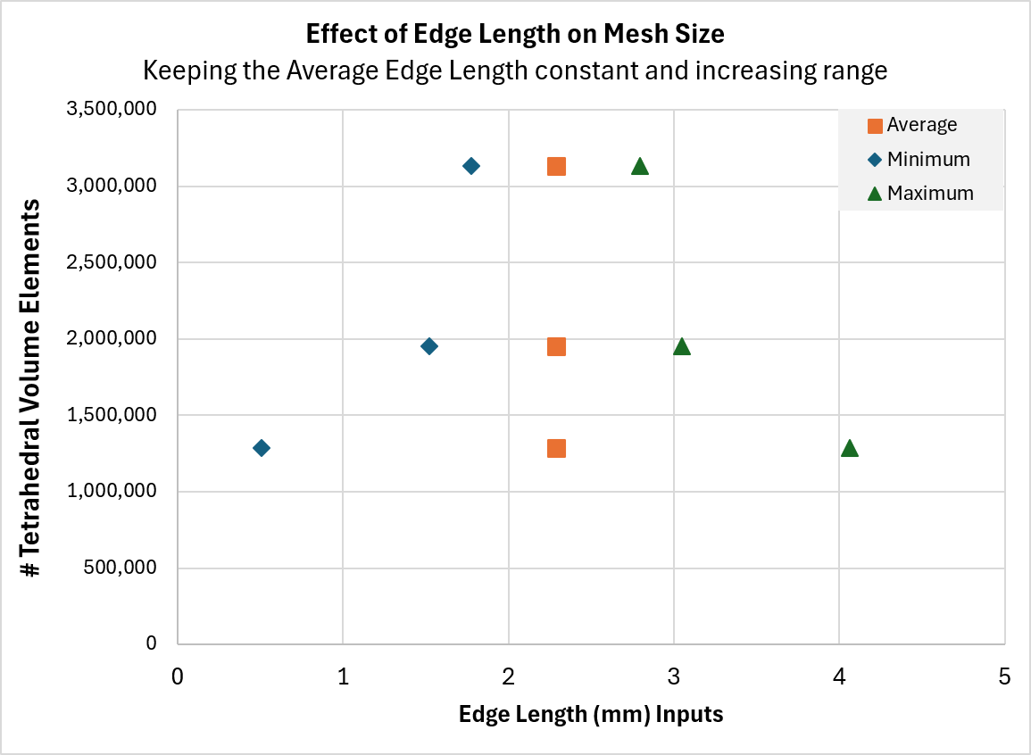
Effect of minimum and maximum edge length on mesh size.
With minimum edge length held constant, increasing the maximum reduces tetrahedral count. For a given average edge length, tightening the (min, max) range increases mesh size. How much the count changes depends on the part’s overall geometry and features.
As noted in Meshing, keep Min Edge Factor near 2 when through-thickness (build-direction) toolpath effects matter.
For the effect on the predicted results, see Example: mesh refinement on a thin-walled clamp.