![3_Transparent_Image_footer.png]](https://novineer.com/hs-fs/hubfs/3_Transparent_Image_footer.png?height=32&name=3_Transparent_Image_footer.png)
Which load type to use when, how to apply different types of loads and restraints directly on a surface and from a remote point, and what effects are captured.
In the Loads & Restraints workflow, expand a load and use the Type section. Choose one of:
| Type | Use when |
|---|---|
| Force | You know a push or pull (weight, bolt load, actuator force, or a pressure resultant treated as a single force). |
| Moment | You know a torque (motor torque, wrench, or twist about a joint) and do not want a net force, unless you also enable Include force. |
| Pressure | You know a uniform surface pressure normal to the loaded faces, for example hydraulic or fluid pressure, or mechanical pressure when using FDM parts as a forming die or tool. For forming and stamping applications, real die contact may be non-uniform; you may need two Shape regions (for example two cubes), split faces, or multiple loads for accurate modeling. |
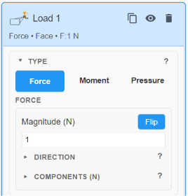
The Type selector of a load: Force, Moment or Pressure.
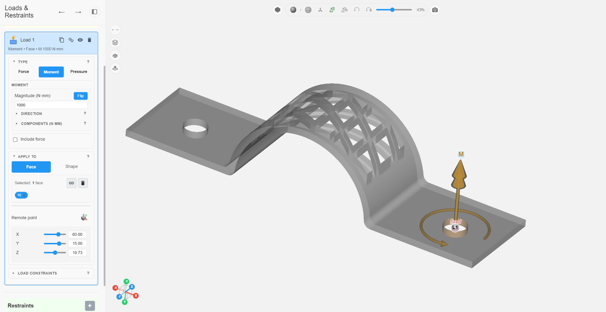
A load (here a moment) applied by Face selection on the clamp example.
Force and moment components are entered in the tray (global) X, Y, Z system, not along the surface normal. The exception is Pressure, which always follows the surface normal (default Into solid; Flip for Out of solid).
Force
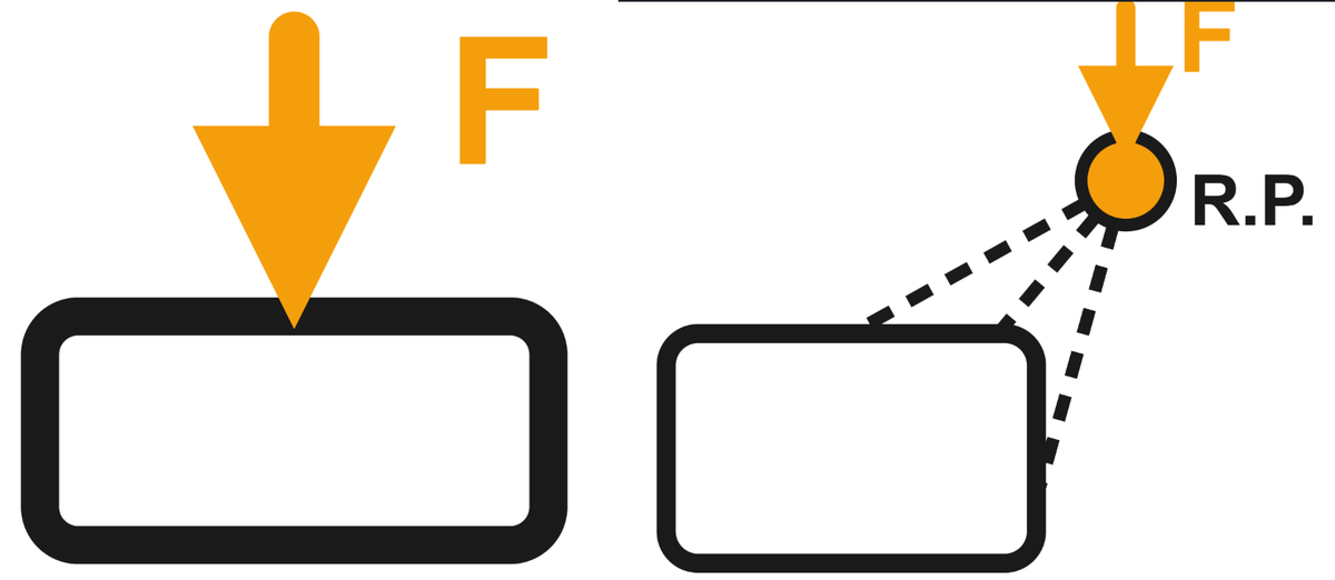
Left: a force applied directly to the selected faces. Right: a force applied at a remote point (R.P.) and transferred into the part.
Use Force when you know a directional push or pull.
- Enter magnitude in N, or set components FX / FY / FZ.
- Set direction with tray X / Y / Z, Normal (one planar face), Axis (parallel cylindrical holes), Aim, or Flip.
- Apply the load to Face selection or a Shape volume (Cube, Cylinder, Sphere).
By default the force is applied directly to the selected faces or shape. To apply it at an offset location, turn on Apply at a remote point (see Remote point below).
Moment
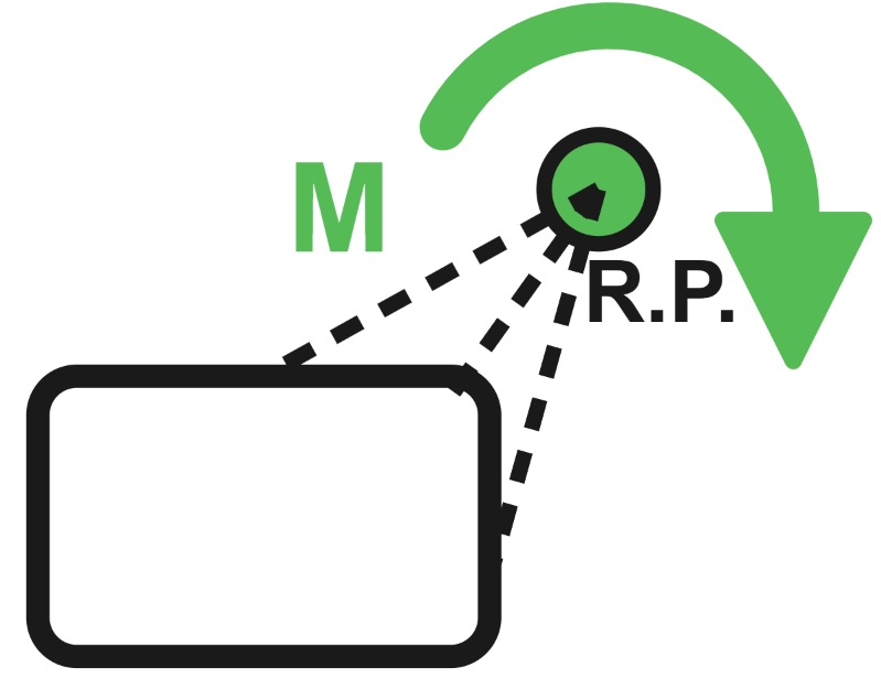
A moment (M) is applied about a remote point (R.P.) rigidly coupled to the selection.
Use Moment when you know a torque and want a pure rotational load (no net force).
- Moments are always applied about a remote point rigidly coupled to the selection.
- Enter magnitude in N·mm, or set MX / MY / MZ.
- Set the rotation axis with the same direction tools as Force (Aim, tray axes, Normal, Axis, Flip).
Note: Do not treat the Moment fields as a moment arm. Those values are applied as moments about the remote point (and through the coupled nodes). If the physical situation is a force acting at a location, use Force with a remote point, not the Moment component fields as an “arm”.
To apply both a torque and a translational force at the same remote point, enable Include force. That shows the Force vector controls under the moment. Direction and magnitude for the moment and the force vector can be adjusted independently by enabling the corresponding Aim button.
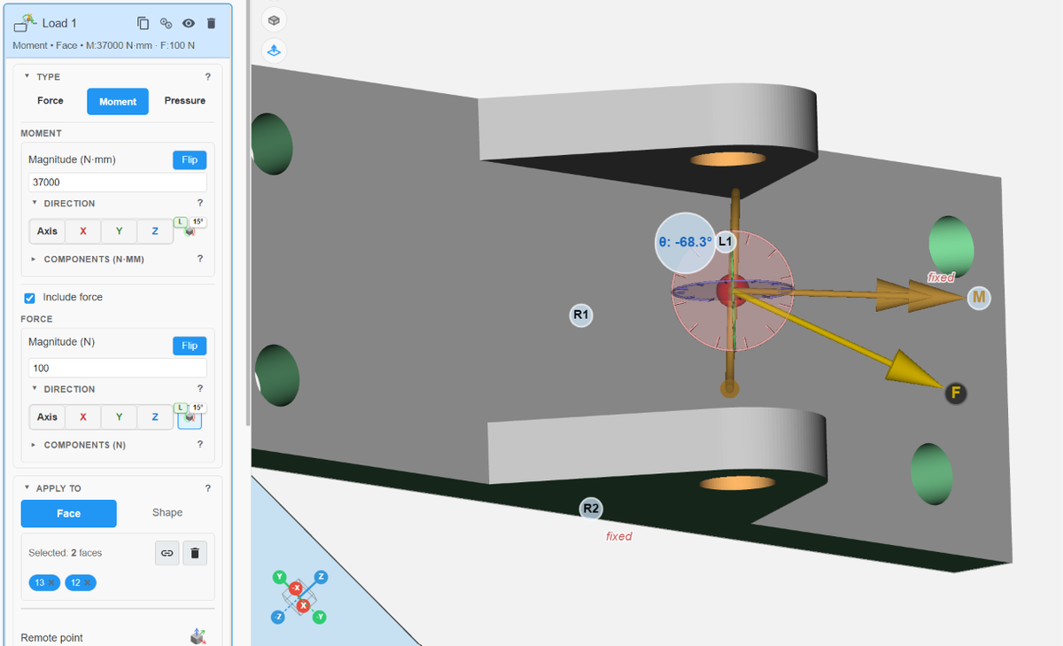
A moment with Include force enabled: the moment axis and the force vector are set independently.
Pressure
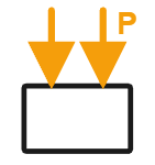
Pressure (P) acts normal to the loaded faces.
Use Pressure when you know a uniform surface pressure normal to the loaded faces (for example hydraulic or fluid pressure, or mechanical pressure when using FDM parts as a forming die or tool).
- Magnitude is always positive, in MPa (N/mm²).
- Direction follows the surface normal. Use Flip to switch between Into solid (inward), the typical hydraulic or compressive pressure, and Out of solid (outward), a suction or tensile pressure.
- Remote point is not available for Pressure (direct surface load only).
- Prefer Face mode for accuracy. Shape mode can miss some surface facets near the region boundary.
- In Face mode, the UI can show the loaded area and an equivalent total force hint (A: … mm², F: … N).
For die-type applications, note that real die contact may be non-uniform; you may need to split faces or use multiple loads for accurate modeling.
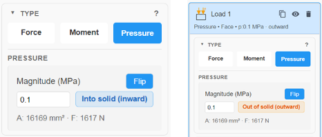
Left: Pressure set to Into solid (inward). Right: after Flip, Out of solid (outward). The loaded area and the equivalent total force are shown below the magnitude.
Inward (positive) pressure
Positive pressure acts into the surface, along the negative direction of the surface normal.
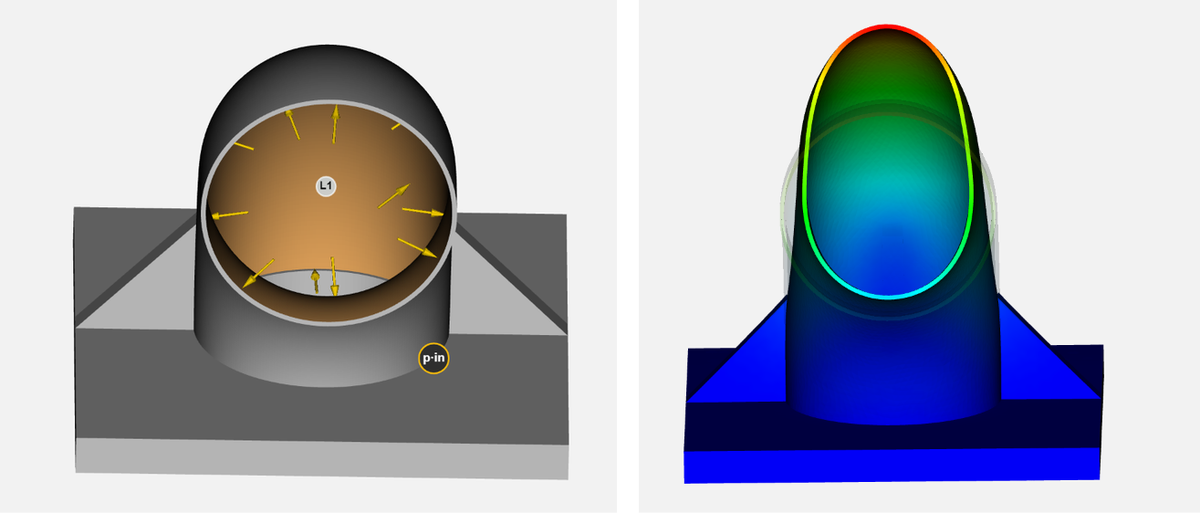
Inward pressure applied to the inside wall of a duct (left) and the resulting displacement (right). Inward here refers to the pressure acting with respect to the normal of the wall surface, which in this case pushes the duct wall outward.
“Inward” pressure is defined as force applied opposite the surface’s outward normal. On convex surfaces (like the arch on a clamp), that intuitively means pressing into the part. On concave surfaces (like a bore or duct), the outward normal points toward the axis, so “inward” pressure actually pushes the wall material away from the axis, visually appearing to point outward.

Inward pressure on the convex arch of the clamp presses into the part.
Outward (negative) pressure
Negative pressure acts outward from the surface, along the direction of the surface normal. Use the Flip button to switch between inward and outward pressure.
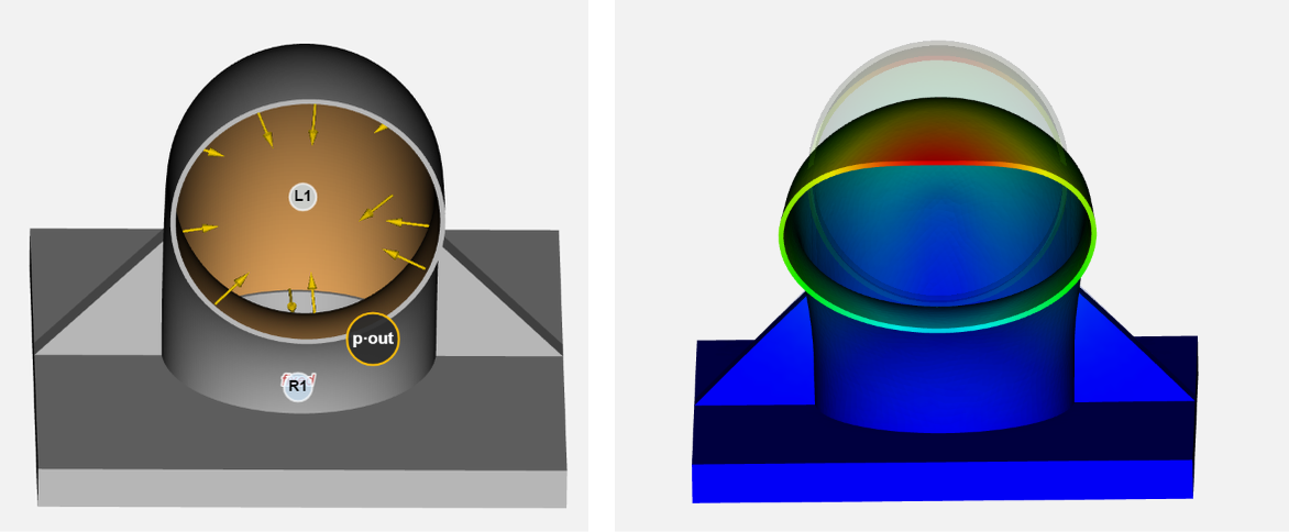
Outward pressure on the inside wall of the duct (left) and the resulting displacement (right).
Outward pressure pulls at the surface along its normal direction. In the case of a duct it acts away from the wall of the solid and hence into the duct passage.
Quick chooser
| You know… | Choose |
|---|---|
| A push or pull (N) | Force |
| A torque only (N·mm), no net force | Moment |
| Both torque and force at the same offset point | Moment + Include force |
| A force at an offset location (lever arm, cable attach, grip point) | Force + Apply at a remote point |
| Uniform surface pressure (MPa) | Pressure |
| Connection that carries force and moment (mount, shaft, fastener) | Moment + Include force, or separate Force and Moment loads |
Units and coordinate system
NoviPath currently supports only the SI unit system (N, mm, kg).
| Quantity | Unit |
|---|---|
| Force | N |
| Moment | N·mm |
| Pressure | MPa |
| Length / remote point | mm |
Force and moment components are in tray (global) XYZ. Pressure defaults to Into solid (opposite the outward normal); Flip switches to Out of solid (along the outward normal).
Remote point
A remote point is a coupling location shown as a red sphere. The selected faces or shape are rigidly tied to that point (all six DOFs). The remote point is the center about which the moment is applied (for Moment), or the point at which a Force is introduced and then transferred into the part.
When to use it
| Situation | Setting |
|---|---|
| Force applied on the selected surface or volume itself | Force, remote off (default) |
| Force acting through an offset (lever arm, cable or rope attachment, bolt or insert, actuator, handle grip, payload center of mass, tool center) | Force + Apply at a remote point |
| Torque about a known center | Moment (remote is always on) |
| Torque and force at the same center | Moment + Include force |
| Pressure on a surface | Pressure (remote not used) |
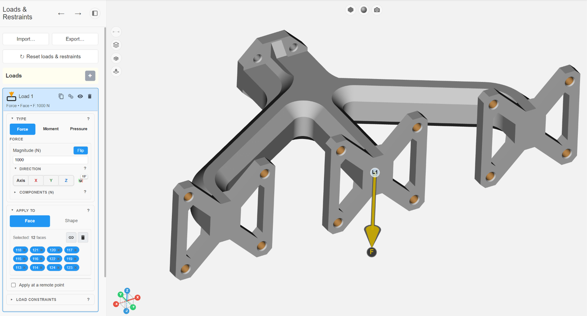
Apply at a remote point is not selected: the load is applied directly on the surface and distributed uniformly among the nodes.
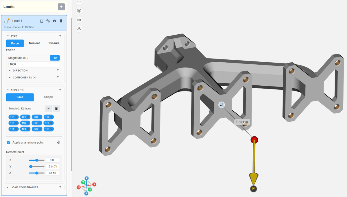
Apply at a remote point is selected: the force is introduced at the red sphere and transferred into the part through the coupled faces.
How to place remote points
- For Force, check the Apply at a remote point checkbox. For Moment, the remote point is mandatory and the block is always shown.
- Set Remote point X, Y, Z (tray coordinates), or use Move and Ctrl+drag the red sphere in the viewport.
- In Shape mode, Use shape center snaps the coupling point to the shape center (and enables remote if it was off). Move it afterward for an offset tool center or payload center of mass.
Load constraints
Load constraints (optional inputs on a load) restrict motion at the load point. This is not a separate restraint; it travels with the load. Choose None for a free force or pressure with no motion limit.
Typical uses: sliding rails, guided actuators, or any load that must stay on a track while still applying force.
| Option | Meaning |
|---|---|
| Pinned | Hold all translations; rotations stay free (clevis or ball-joint style). A force or moment can still be applied. |
| Slide | Same resolution as the restraint Slide: Face + planar + direct = Guided (one in-plane direction; rotations free); Face + shared cylinder axis = Cylindrical (slide + spin); remote, Shape or mixed = one free direction with rotations fixed. See Restraint types. |
| None | No motion limit; the loaded region stays free while the load is applied. |
| Custom | Pick Fixed/Free per DOF in View. Prefer Slide when one free axis is enough. |
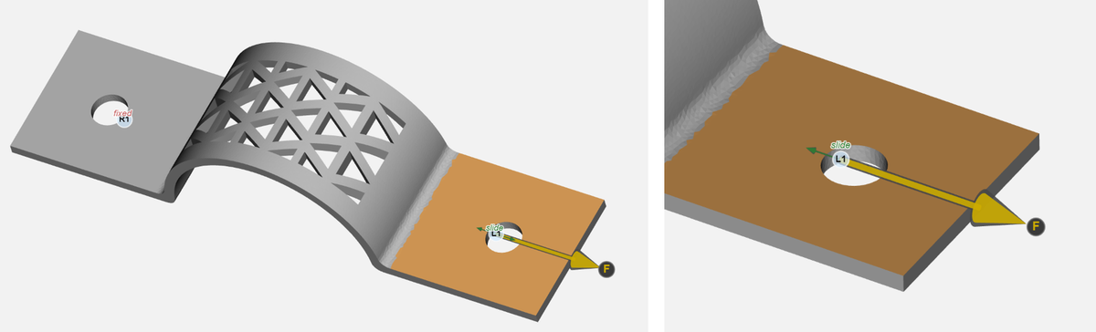
A directional force on the top planar face at the right end of the clamp, with a Slide load constraint (left) and a close-up of the slide direction (right).
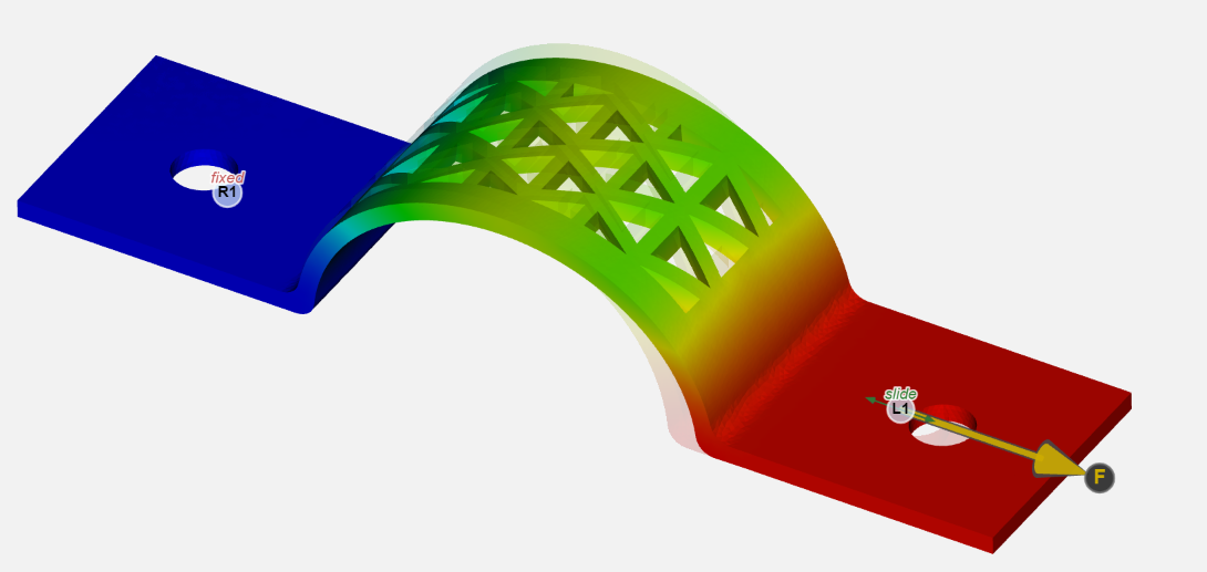
The resulting deformation. The sliding constraint allows the in-plane displacement along the load direction but prevents all other lateral (horizontal) and normal (vertical) movement.
See also Face selection vs. Shape: where loads and restraints apply and Restraint types: Fixed, Pinned, Roller, Slide or Custom.