![3_Transparent_Image_footer.png]](https://novineer.com/hs-fs/hubfs/3_Transparent_Image_footer.png?height=32&name=3_Transparent_Image_footer.png)
This walkthrough runs one complete simulation on the end-of-arm-tool part shown in the screenshots. Each step ends with a link to the article that explains it in full; you do not need those articles to finish the walkthrough. Before starting, make sure the plugin is installed and licensed (Install the NoviPath plugin for GrabCAD Print).
Open the Part in GrabCAD Print- Open your GrabCAD Print project.
- Place a single part on the tray. NoviPath currently simulates one part. If multiple models are on the tray, only the first model added is analyzed.
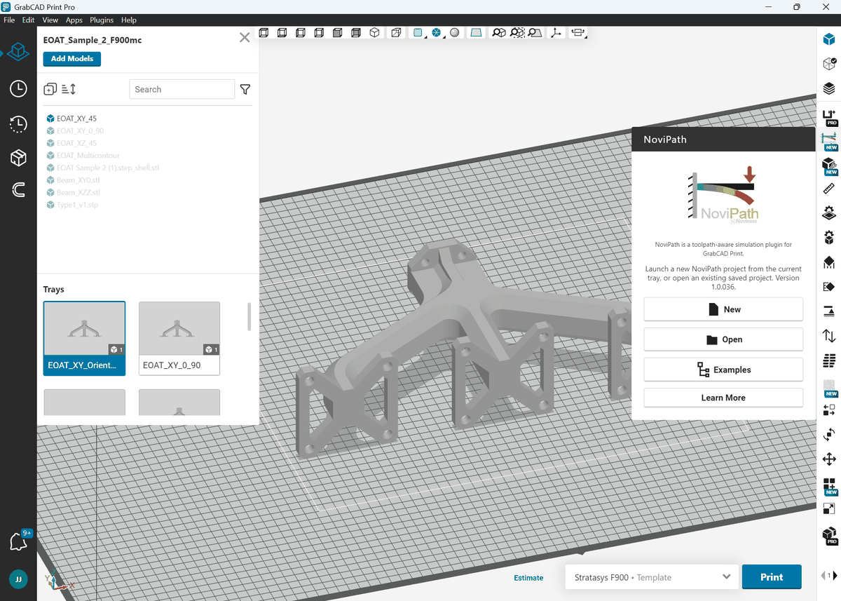
NoviPath analyzes the first model from the Grabcad Print tray.
Create a NoviPath Project- Open the NoviPath panel on the right and select New project.
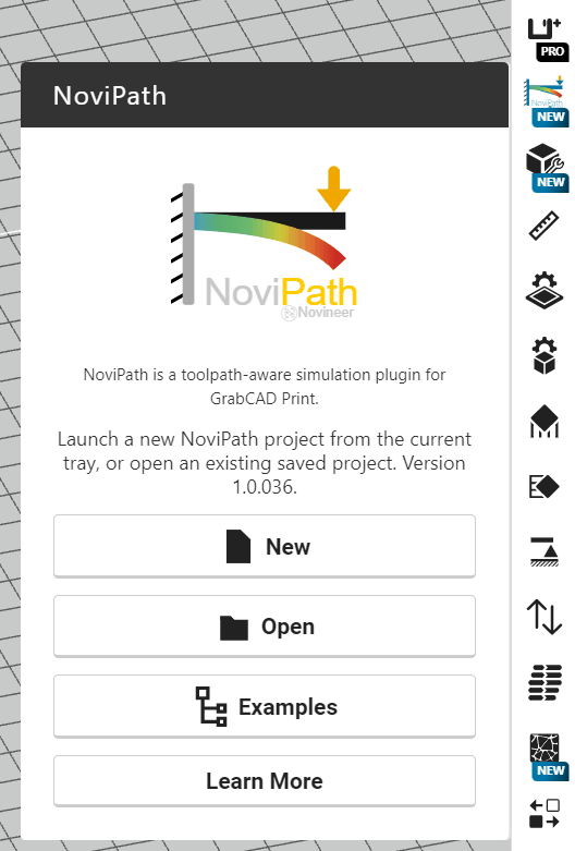
Quick access to NoviPath
- Enter the project bundle name. The default name is the GrabCAD Print tray name plus the suffix *_novipath*, so NoviPath folders stay separate from print files. In the example below, the tray name is “EOAT_XY_Orientation”, so the default bundle is “EOAT_XY_Orientation_novipath”.
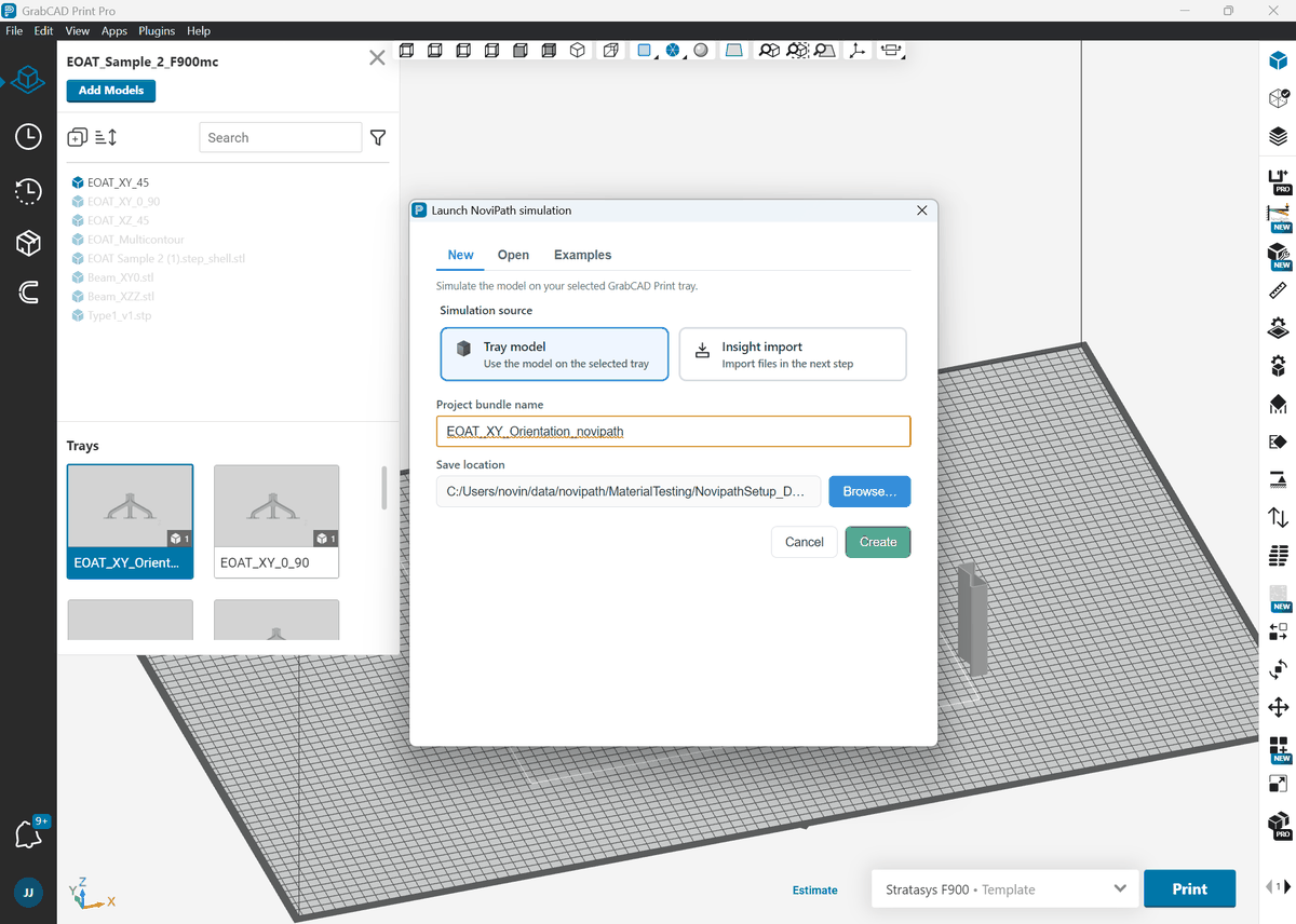
NoviPath project bundle and default naming convention
- After adjusting the project name, click Create.
- Plugin data preparation starts as soon as you click Create. It finishes before the plugin window is shown.
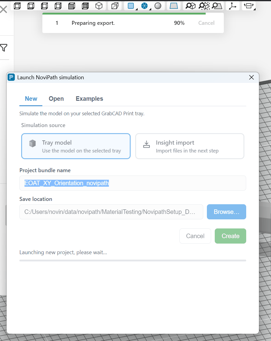
Plugin data preparation runs before the plugin window opens.
- If you have already sliced the part in GrabCAD Print, GrabCAD Print only needs to export the toolpaths in a format the plugin can read.
- If the part has not been sliced, GrabCAD Print slices it first and then sends the data to the plugin. This can take several minutes for large parts.
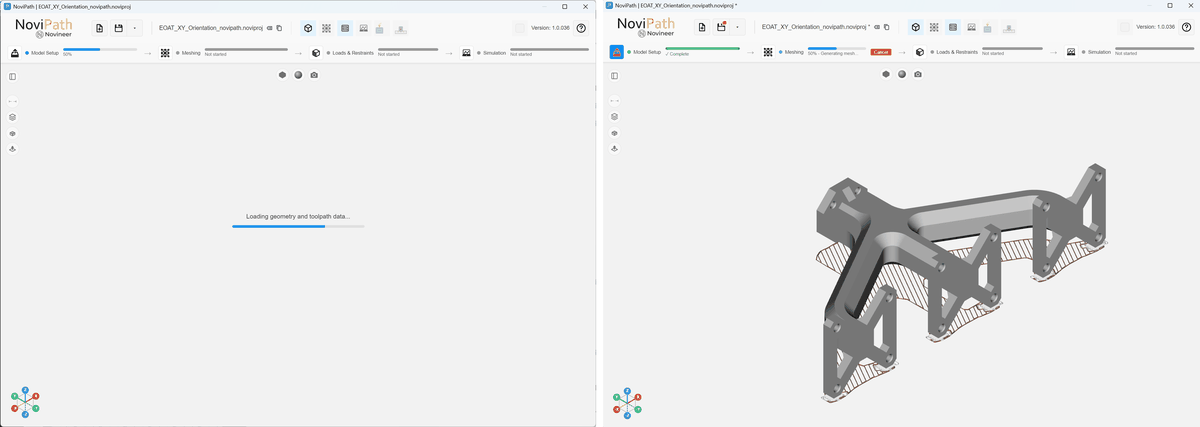
Left: plugin starting. Right: model and toolpaths loaded, meshing in progress.
- After the plugin window opens, the geometry and toolpaths load. Finite-element meshing starts in the background so you can continue setting up the model, including loads and restraints to save time. Although you can edit loads while meshing runs, you cannot start the simulation until both meshing and Loads & Restraints are complete.
- When background meshing finishes, the finite-element mesh is displayed in steel blue. The viewer shows the outer surface of that mesh, not the interior tetrahedra, to keep memory use and viewer performance acceptable. The volume mesh is still generated and used by the solver.
- Click the third step on the Workflow status bar: Loads & Restraints.
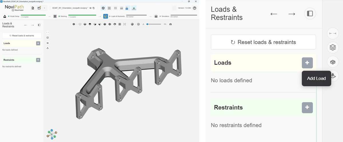
Apply loads and restraints
- Click the + button to add a load. Use the default Face selection, or switch to Shape if you need to apply the load to a geometric region.
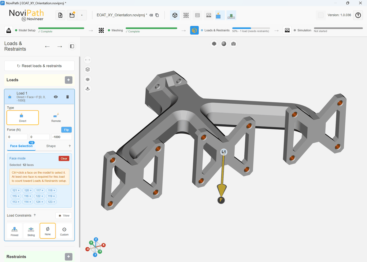
Selecting faces to apply loads
The 12 faces highlighted in gold were selected so a uniformly distributed load can be applied. The total load F = (0, 0, −1000 N) is distributed evenly over the surface nodes of those faces.
- Decide whether the loaded nodes also need a load constraint. If they do, choose an appropriate Load constraint.
- As with loads, click the + button to add a restraint.
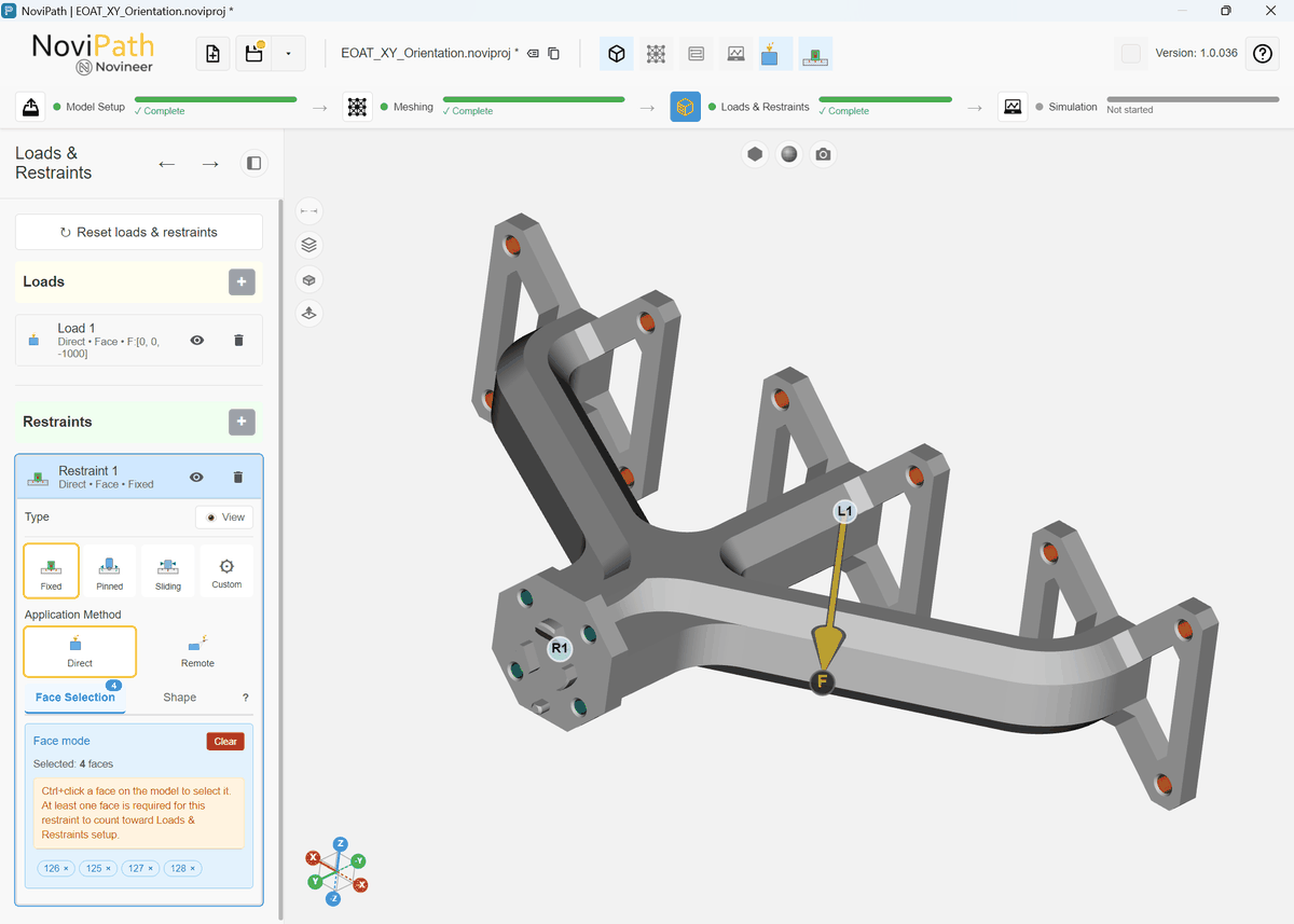
Selecting faces to apply restraints
The four faces highlighted in green (#126, #125, #127, and #128) were selected for a Fixed restraint.
Run the Simulation- After loads and restraints are fully specified, click the Simulation step on the Workflow bar.

The Simulation step on the Workflow bar.
- Click Run Simulation to run the solver and view the results.
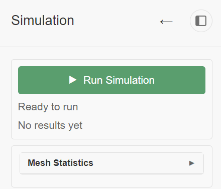
Run Simulation.
- When the simulation finishes, the results are loaded and contour plots are shown. Use the controls in the left-hand panel to inspect stresses and displacements.
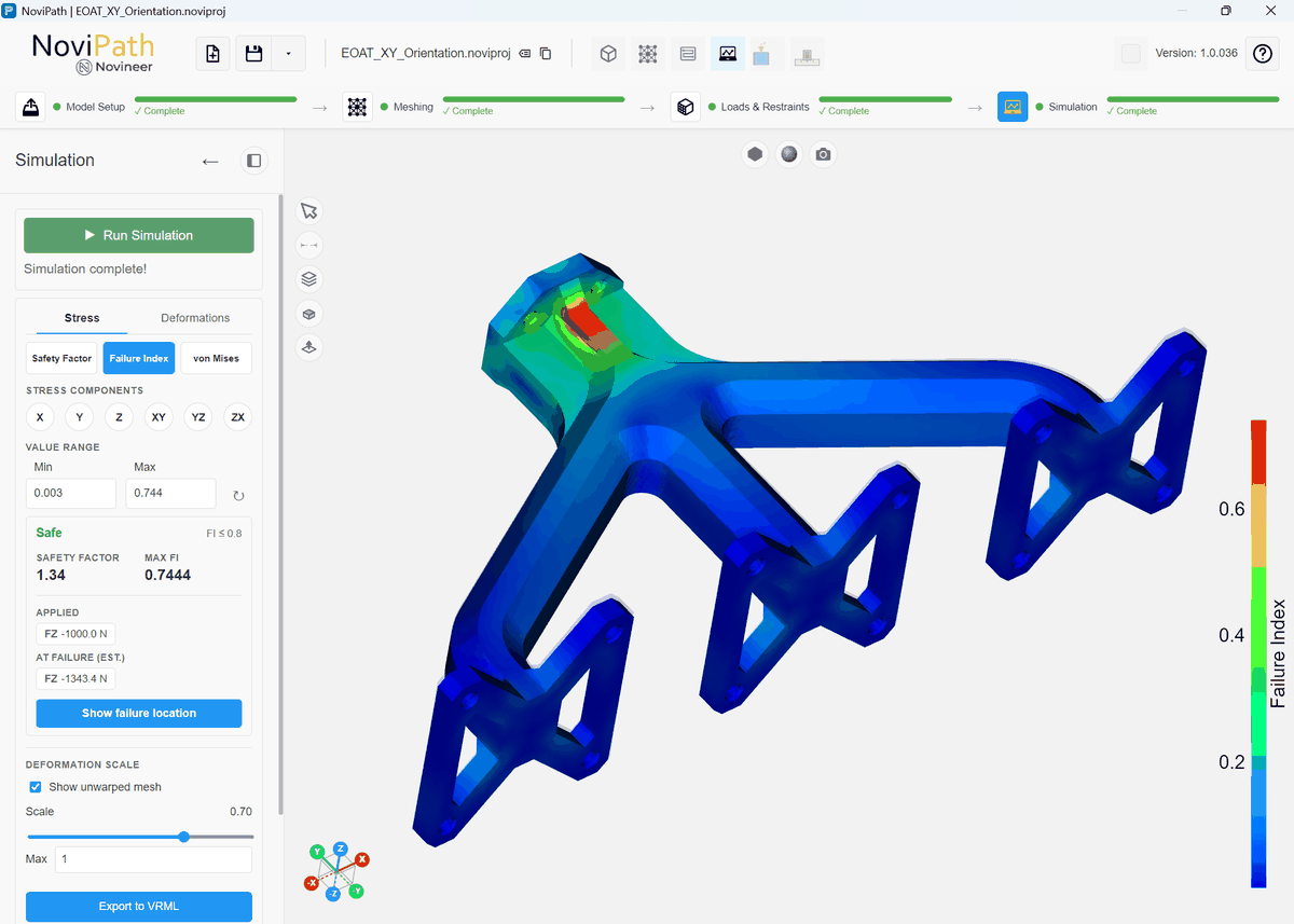
Simulation results view showing Failure Index
Learn more: The project bundle and its files · How NoviPath meshes your part · Face selection vs. Shape: where loads and restraints apply · Restraint types and degrees of freedom · Reading your first result